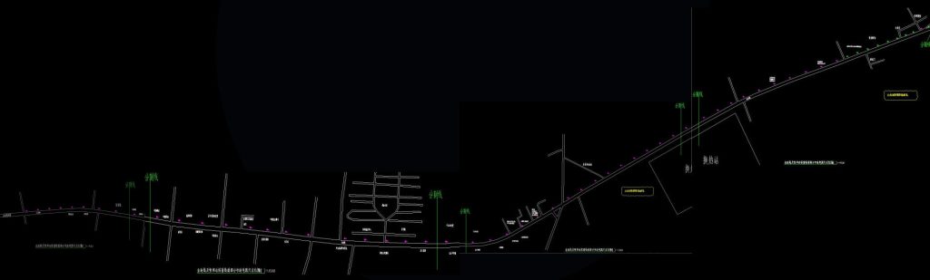
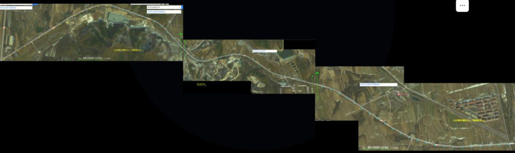
Project location
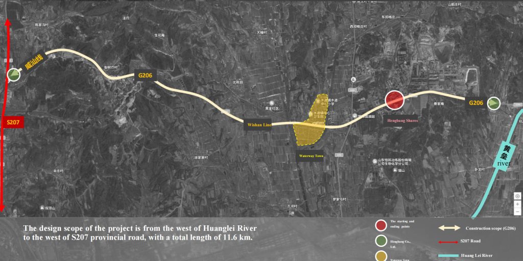
The scope of this design: it starts from the west side of Huanglei River in the east and ends at S207 Provincial Highway in the west, with a total length of 11.6 kilometers.
Current situation analysis
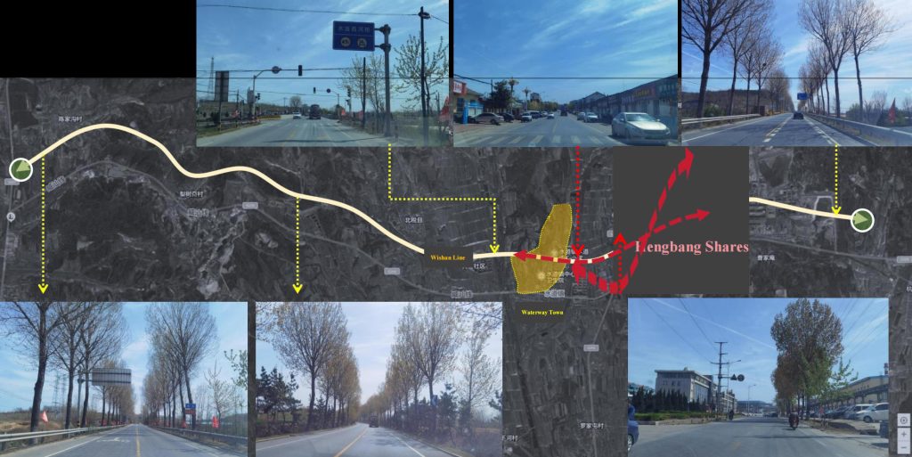
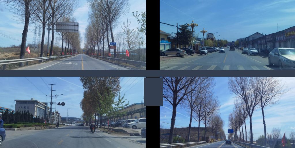
Features of the project: the whole section is 1 2 kilometers, the distance is far away, there is no power supply cable at present, the lighting of electric lamps is used, and the cost of laying lines is high. Vegetation characteristics: tall, dense and continuous, with high construction difficulty.
Project Positioning
Nature-oriented | Function-oriented | Management-oriented
Optical continuity of road lamp Meet the basic functional lighting requirements at night.
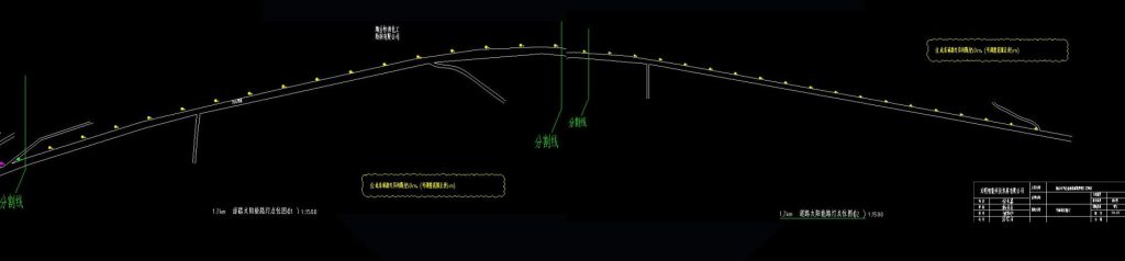
Deployment Strategy
Based on the current road conditions, the following layout strategies are proposed:
A section of ahighway or railway | Type | Name | Quantity |
First paragraph Upstream K76+ 329.009-K78+080.978 | Add streetlights | Single-head solar street lamp | 34 |
The second paragraphUpstream K78+080.978-K80+828.051 | Add streetlights | Single-head solar energy municipal integ-rationStreetlight | 46 |
On-site retention | Streetlight mai-ntenance | 10 | |
Paragraph 3Downward K80+828.051-K87+935 | Old street lighting | Single head solar Streetlight | 46 |
Add streetlights | Single-head solar street lamp | 25 |
Plan Description
The road lighting upgrade project in Shuidao Town, Muping District, involves the G206 Weishan Line, stretching approximately 11.6 kilometers from the west side of Huanglei River to Provincial Highway S207. The project will install high-efficiency solar streetlights and hybrid streetlights (with selected models and renderings attached), divided into three construction phases.
1 、 The road section from the west side of Huanglu River to the entrance of Hengbang Co., Ltd. (upstream K76+329.009-K
78+080.978) is about 1 8 kil.om.eters, and the lamp spacing is arranged according to 50 meters, and 34 solar street lamps need to be installed.
2 、 The section from the entrance of Hengbang Co., Ltd. to the west river of the waterway (upstream K78+080.978-K80+828.051) is about 2.7 kilometers. The construction of the original street light foundation and power supply will be used to install 56 solar power and mains electricity integrated street lights.
3 、 The waterway from the West River to the S 207 provincial road section (downward K80+828.051-K87+935) is about 7.1 km, and the lamp spacing is arranged according to 100 meters, and 70 solar street lamps need to be installed.
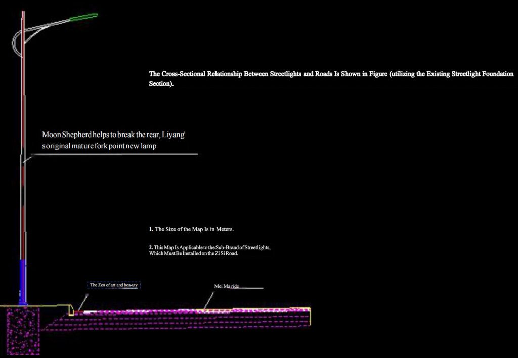
Scheme design (first section upstream K76+329.009-K78+080.978)
This section spans approximately 1.8 kilometers from the entrance of Hengbang Co., Ltd. to the Shuidao West River, utilizing existing streetlight foundations and power supply infrastructure for installation work.
Among Them, 34 New Single-Head Solar Street Lamps Were Added.
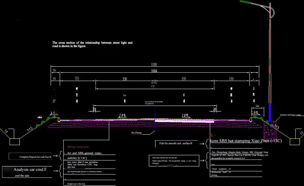
Scheme design (second paragraph K78+080.978-K80+828.051)
The 2.7-kilometer stretch from the west bank of the Huanglu River to the entrance of Hengbang Co., Ltd. features 50-meter spacing between streetlights.
The plan includes installing 46 new single-head solar-powered integrated municipal streetlights while maintaining 10 existing ones.
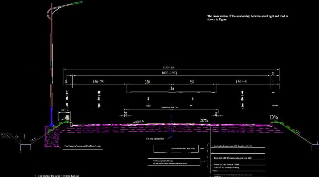
Solutiondesign(thirdsegmentdownlinkK80+828.051-K87+935)
This section spans approximately 7.1 kilometers from Shuidao Xihe to the provincial road S207, with streetlights spaced 100 meters apart. A total of 70 solar-powered streetlights will be installed.
The project includes 25 new single-head solar streetlights and 46 single-head solar streetlights (for urban renewal).
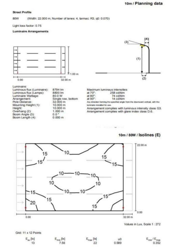
Lighting Design
Parameter :
Solar energy: High-efficiency imported monocrystalline silicon; Battery: High-efficiency lithium iron phosphate battery with a lifespan of over 25 years and over 10 years.
Power: 120W LED light source
Color temperature: 4000K
Light source type: LED module combination
Material: Q235B carbon steel
Light source: LED imported
Pole Process: Hot-dip Galvanizing and Fluorocarbon Coating
Ambient temperature: -30℃~+70℃
Light efficiency: 160-170lm/W
Light angle: wide angle
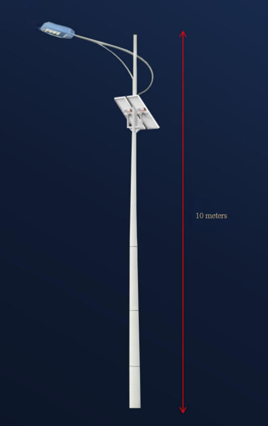
Lamp height: 10m
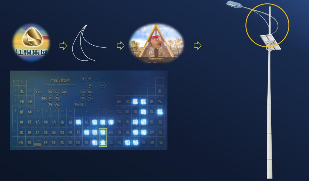
The company’s main products are gold, silver (lighting color)
“Concept, technology and management”three major innovations(lighting elements)
Three strategic goals: ” full productization of valuable elements, zero waste of green development, and unmanned production operation
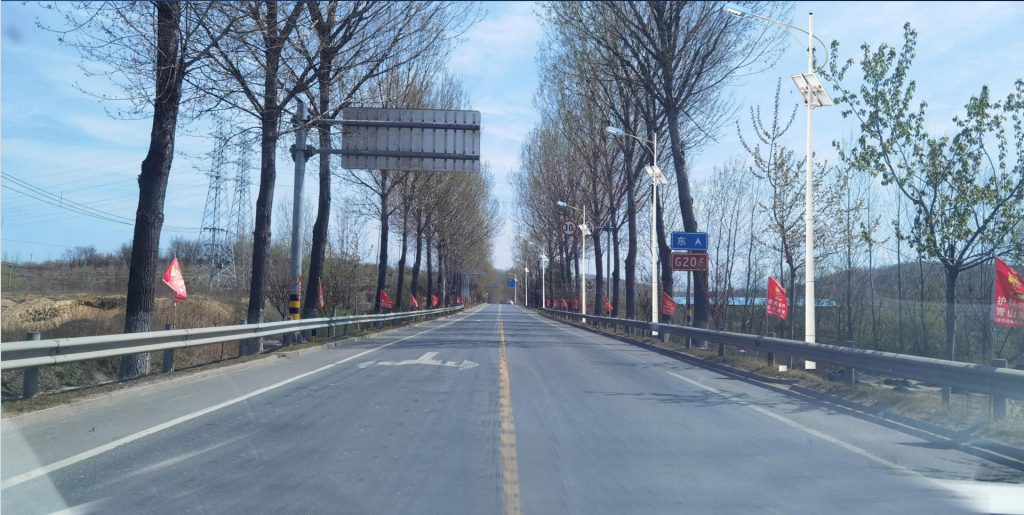
Effectiveness exhibition demonstration
Daytime effect
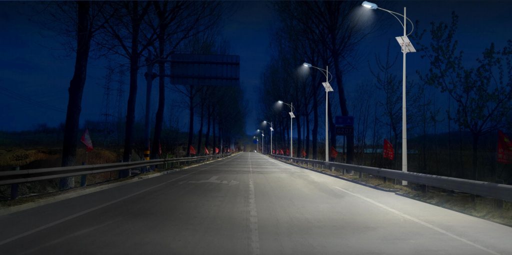
Night effect
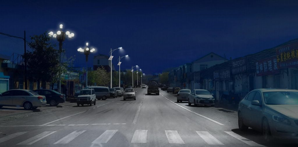
Night effect
Tec-hnicalcontrol
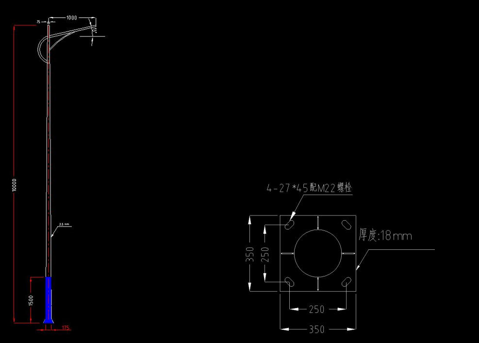
Technical Description :
1 、 This drawing uses mm as the unit;
2 、 The cross-section of the pole is circular;
3 、 The main rod is made of Q235 high quality steel plate, which is bent by large bending machine and then welded.
4 、 The diameter of the lamp post is 75~ 175mm, the wall thickness is 3.5mm, and the flange is 350×350×18mm.
5 、 The full set of pole anticorrosion treatment is hot-dip galvanized pipe + spray paint treatment, the thickness of spray paint layer is more than 70μm. The spray paint color is white + blue;
6 、 The lamp is an integrated solar lamp.
Technical Parameters
Calculation Basis and Basic Parameters
1.1 Basis for Design Specifications
Code for Design of Building Foundation and Substructure (GB 50007-2011)
Highway Subgrade Design Code (JTG D30-2015)
Code for Design of Concrete Structures (GB 50010-2010)
Design Standard for Urban Road Lighting (CJJ 45-2015)
1.2 Lamp Post Parameters
Light pole height: 10m
Upper diameter: 75mm, lower diameter: 175mm, wall thickness: 3.5mm
Flange: 350mm×350mm
Material: Q235 steel
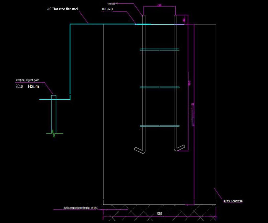
1.3 Basic Parameters
The foundation dimensions are 1000mm×1000mm×1600mm, with C25 concrete. The soil at the foundation base is compacted to a density of ≥97%, meeting the standard for highway subgrade compaction.
The cage structure consists of 4 flat steel bars, M22 bolts, with a concrete anchorage length of 1200mm and protruding 80mm above the foundation top surface.
1.4 Geological and Load Parameters
bulk density: γ= 19 kN/m³
cohesivity: c=25kPa
Internal friction angle: φ=30°
Base width: b= 1.0m, Base depth: H= 1.6m
Special verification of the two ground cage anchoring systems
2.1 Confirm the Total He-
ight of the Floor Trap:
1280mm
Anchor bolts: 4 M22, Q235 steel
Concrete cover thickness: ≥50mm
2.2 Verification of Anchoring Length
According to the Code for Design of Concrete Structures:
M22 bolt diameter: d=22mm
C25 concrete axial tensile strength: f_t= 1. 1N/mm2
Q235 steel bar tensile strength: fy=235N/mm²
Basic anchorage length: I_ {ab}=α×(f_y/f_t)×d
=0.14× (235/1.1) ×22=658mm
The actual anchoring length of 1200mm exceeds the standard requirement of 658mm, meeting all specifications.
2.3 Verification of the Load-bearing Capacity of the Ground Cage
Bond strength of concrete and steel: T_b= 1.5N/mm2 (C25 concrete)
The bonding area of a single bolt is calculated as: A_b= π × d × l_a =3.14 × 22 × 1200 = 82,896 mm² . The pull-out bearing capacity of a single bolt is calculated as: F_b=t_b × A_b= 1.5 × 82,896 = 124,344 N. =124.3kN
Total pull bearing capacity: 4×124.3=497.2kN
2.4 Calculation of Bolt Tension
Flange dimensions: 350mm×350mm
The center distance of the bolt is d=250mm.
Tilt moment: M=4.21kNm
Vertical load: N=39.7kN
Maximum bolt tension:
T_max=M/(n×d)-N/n
=4.21/(4×0.25)-39.7/4
=4.21-9.93=-5.72kN (under pressure)
Safety factor: K=497.2/5.72=86.9>2.5, safety 3 load calculation
3.1 dead load
( o lated as a frustum:
=3. 14×0.0035×(0.075+0. 175)×10/2
= 0.0137m³
Light pole weight: G1 =0.0137×7850×9.8/1000= 1.05kN
Lamps and accessories: G2 =0.25kN
Base weight: G3 = 1.0×1.0×1.6×24=38.4kN
Total vertical load: N= 1.05+0.25+38.4=39.7kN
3.2 Wind Load Calculation
50-year basic wind pressure in Yantai: Wo=0.55kN/m2
Standard wind load value:
w_k= β_z×μ_s×μ_z×Wo
β_z=1.0 (wind vibration coefficient)
μ_s=0.8 (body mass index)
μ_z=1.0 (wind pressure height variation coefficient)
w_k=1.0 ×0.8 × 1.0 ×0.55=0.44kN/m²
wind area :
Wind area of lamp post A_d=(0.075+0. 175)×10/2= 1.25m 2; wind area of lamp A_I= 0.2m 2 total wind area A= 1.45m 2
Total wind load: F_w=0.44×1.45=0.638kN
Tilt moment: M=0.638×(10/2+1.6)=0.638×6.6=4.21kN·m
Special calculation for slope stability
4.1 Influence of foundation on slope stability
The foundation is located on the slope, and it is necessary to check whether it will cause the slope to be unstable.
4.2 Slope Stability Safety Factor
The simplified Bishop method is used to analyze the slope stability.
Slope angle: 33.7° (1:1.5)
Safety factor: Fs= (c + yHcos²βtanφ) / (yHsinβcosβ)
-Fs=(25+19 × 1.6 ×cos233.7 ° ×tan30°)/(19 × 1.6 ×sin33.7 ° ×cos33.7 °)
-Fs=(25+19 × 1.6 ×0.692 ×0.577)/(19 × 1.6 ×0.555×0.832)-Fs=(25+12. 14)/(14. 11)=37. 14/14.11=2.63>1.3 Conclusion: The stability of the slope itself meets the requireme-nts.
5 Basic anti-rolling stability calculation
5.1 Anti-tipping moment composition
Base self-weight anti-tipping moment:
M_r1=38.4 ×0.5= 19.2kN·m
Tilting moment of the pole due to its own weight:
M_r2= 1.3 ×0.5=0.65kN·m
Passive soil pressure calculation:
K_p=tan2(45°+30°/2)=3.0
√ K_p= 1.732
Soil Gravity Section:
E_p1=0.5 ×γ × H²×K_p × b
=0.5 × 19 × 1.6²×3.0 × 1.0=72.96kN
M_r3-1=72.96× 1.6/3=38.91kN·m
Adhesion section:
E_p2=2×c×H×√K_p ×b
=2×25×1.6×1.732×1.0=138.56kN
M_r3-2=138.56×1.6/2=110.85kN·m
Total passive earth pressure moment:
M_r3=38.91+110.85=149.76kN·m
5.2 Total Anti-Toppling Moment and Safety Factor
Total anti-tipping moment: M_r=19.2+0.65+149.76= 169.61kN·m
Anti capsizing safety factor: K= 169.61/4.21=40.29>1.5
Conclusion: Anti capsizing stability meets the requirements.
Calculation of foundation bearing capacity
6.1 Calculation of substrate pressure Base area: A= 1.0×1.0= 1.0m2
Base section modulus: W= 1.0×1.02/6=0. 1667m3
Eccentricity: e=M/N=4.21/39.7=0. 106m
e=0.106m<B/6=0.167m
Maximum base pressure:
P_max=N/A+M/W=39. 7/ 1. 0+4.21/0.1667 =
39.7+25.26=64.96kPa
6.2 Correction of Foundation Bearing Capacity
Modified characteristic value of foundation bearing capacity: f_a=f_ak+η_d×y×(d-0.5)
=180+1.0×19×(1.6-0.5)=180+20.9=200.9kPa
6.3 Load-Bearing Capacity Verification
Requirement: P_max≤1.2f_a =1.2×200.9=241.08kPa
Actual: P_max=64.96kPa<241.08kPa Safety factor of foundation bearing capacity: K=241.08/64.96=3.71>1.0
Conclusion: The bearing capacity of foundation meets the requirements.
Stability check of the foundation pit
7.1 The stability of the foundation pit slope is determined by the
Taylor stability number method.
Steady state number: N_s=γH/c=19×1.6/25= 1.216
Safety factor: Fs= (2c/yH) × tan(45° + φ/2) =(2 ×25/(19 × 1.6)×tan(45°+15°)
=(50/30.4)×1.732= 1.644×1.732=2.85>1.3
7.2 Construction Measures Considering the Influence of the Ground Cage The burial depth of the underground cage should be increased to 1200mm, and the pit wall
support should be strengthened.
-Use a steel formwork support system
- Comprehensive evaluation and conclu- sions
8.1 Summary of Verification Results
Verifying item | Computing result | Standard requireme- nts | Safety factor |
Safety factor for anchor installation in under- ground cages | 86.9 | ≥2.5 | Satisfied |
Slope stability safety factor | 2.63 | ≥1.3 | Satisfied |
Factor of safety against overturning | 40.29 | ≥1.5 | Satisfied |
Safety factor for the bearing capacity of the foundation | 3.71 | ≥1.0 | Satisfied |
Safety factor for the stability of the foundation pit | 2.85 | ≥1.3 | Satisfied |
8.2 Final Conclusions
The basic dimensions of the structure meet the requirements of the code in all kinds of stability tests, and have a high safety reserve.